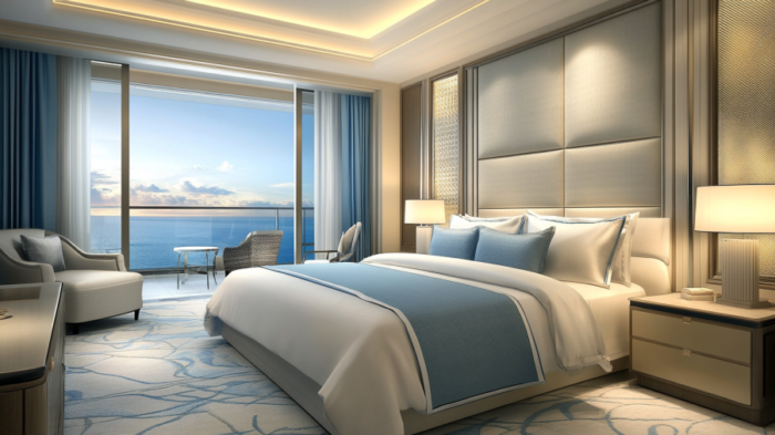
Designing a hotel room is more than just about aesthetics—it’s about creating an experience. In 2025, guests are looking for
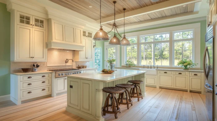
Cream color kitchen cabinets have been a popular choice for homeowners due to their timeless, warm, and inviting aesthetic. They
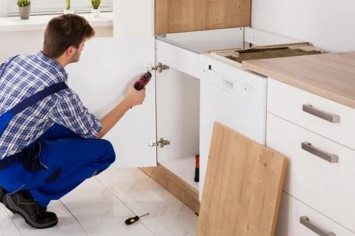
Introduction The kitchen, often touted as the heart of the home, can see a lot of wear and tear over
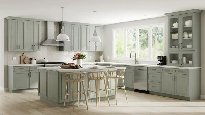
We delve into how PA Home blends timeless Shaker Cabinet design with modern custom features, offering a unique solution for every needs.