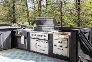
There’s a certain charm that outdoor spaces bring to any home. They are the perfect setting for family BBQs, friendly
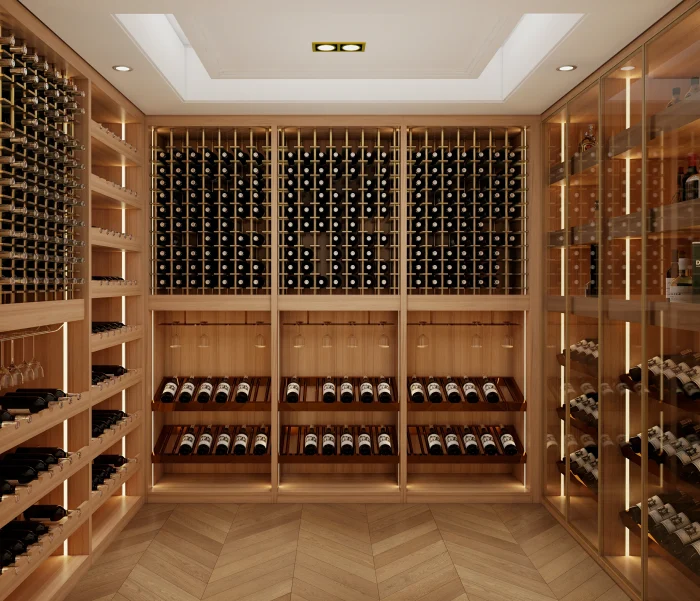
Wine lovers know that proper wine storage is essential for preserving the taste and quality of their collection. Whether you’re
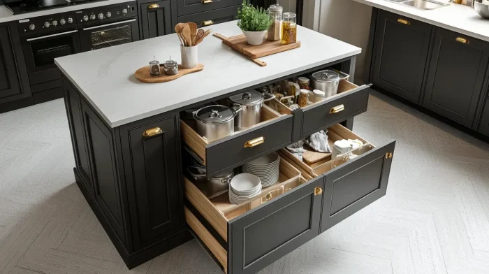
Discover the top kitchen carcass materials, smart storage solutions, and customization options for a durable and stylish kitchen setup.

If you’re considering upgrading your house windows to double glazing, you might be wondering, how much do double glaze windows