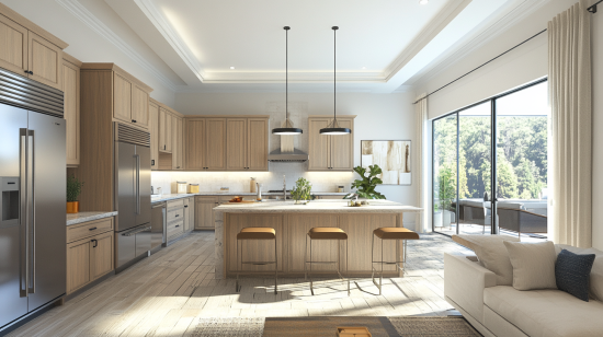
Are you dreaming of a kitchen that perfectly blends natural beauty with long-lasting durability? In this guide, we’ll explore every
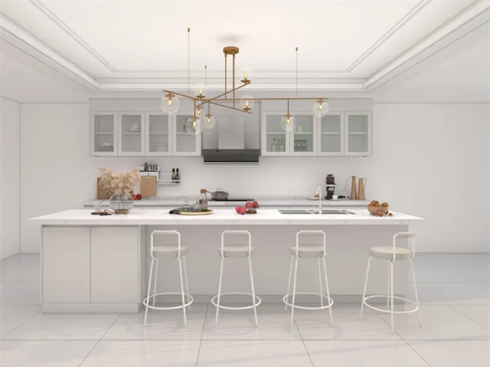
Lacquer kitchen cabinets are a great addition to any kitchen

Looking for affordable small living room decor ideas? Discover space-saving tips, cozy designs, and budget-friendly hacks to transform your compact space.
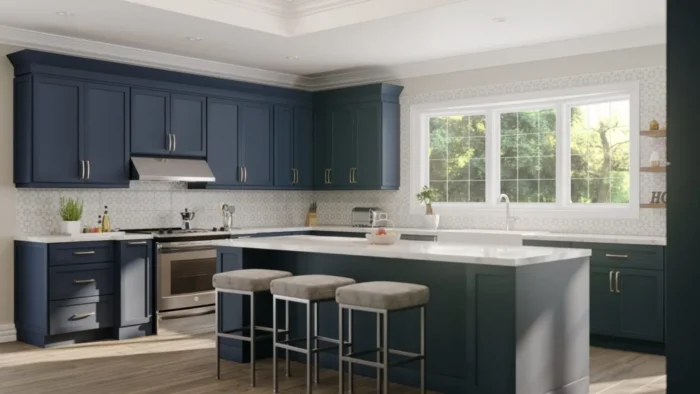
Ready-To-Assemble Cabinets, known as RTA Cabinets in short